The long-term stable operation of the slitting machine is the core of ensuring production efficiency, product quality and cost reduction. Regular, scientific calibration is the cornerstone of maintaining its optimal condition. Below are detailed calibration methods, cycles, and recommendations for key parameters of slitting machines.
Introduction: Why do you need regular calibration?
In the long-term operation of the slitting machine, due to factors such as vibration, wear, material tension changes, and ambient temperature and humidity, the accuracy of its key components will gradually deviate. These small deviations add up and can lead to:
• Reduced slitting accuracy: Problems such as serpentine, burrs, constant cutting, or over-cutting occur.
• Poor winding quality: uneven winding, collapsed rolling, exposed tendons, surface scratches, etc.
• Reduced efficiency: Frequent downtime adjustments increase scrap rates.
• Increased equipment loss: Incorrect parameters can accelerate wear on components such as blades and bearings.
Calibration methods for key parameters regularly
The following breaks down the key systems of the slitting machine and details the calibration method.
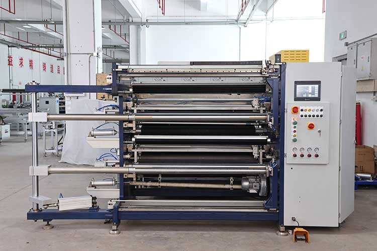
1. Tension control system calibration
Tension is the "soul" of the slitting machine, which directly affects the winding quality and the stability of the slitting process.
• Key components: tension sensor, magnetic powder clutch/brake, servo motor, tension controller.
• Calibration Method:
1. Sensor calibration (zero point and range):
▪ Preparation: Ensure that the discharge and receiving shafts are in a free state without material.
▪ Zero Point Calibration: Execute the "Zero Point Calibration" command on the user interface or controller. At this time, the controller should read and record the current signal value, which is defined as 0 tension.
▪ Range calibration: Use measured standard weight weights (e.g. 1kg, 5kg, 10kg). The weight is suspended vertically and acts on the tension detection arm through a pulley device, allowing the sensor to withstand a precise force.
▪ Enter standard value: Enter the tension value corresponding to the current hanging weight (e.g. 10kg) in the controller.
▪ Verification: Take weights of different weights for multi-point verification to ensure good linearity.
2. Actuator Calibration (Magnetic Powder Clutch/Brakes):
▪ Check for aging or leakage of magnetic powder and replace if necessary.
▪ Set a fixed current value (e.g. 1A) on the controller to measure whether its output torque is consistent with the specification. This operation usually requires professional equipment and is recommended to be performed by an equipment supplier or professional technician.
3. System Response Debugging:
▪ In the case of wearing the material but not cutting the material, the manual step changes the tension setpoint and observes the response curve of the actual value of the tension. By adjusting the controller's PID parameters (scale, integral, differentiation), the response is both fast and smooth, without overshoot or oscillation.
• Recommended calibration interval:
◦ Daily/Shift: Perform zero point checks.
◦ Monthly: Perform simple weight verification.
◦ Semi-annual to one-year: Perform comprehensive calibration and PID parameter optimization.
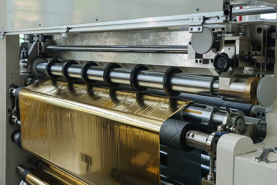
2. Tool system calibration
The precision of the tool directly determines the slitting width and trimming quality.
• Key components: round insert, base cutter shaft (or groove roller), tool loading shaft sleeve, slide seat.
• Calibration Method:
1. Parallelism and Perpendicularity Calibration:
▪ Round-Bottom Cutter Parallelism: Use a high-precision feeler gauge to measure the clearance between the circular knife and the base cutter (or slot roller) across the entire contact surface. Rotate the knife shaft slowly to ensure uniform clearance at any position. Correct by adjusting the base cutter shaft or the eccentricity mechanism of the round tool holder.
▪ Round Knife-Bottom Knife Cutting Volume: Set the appropriate cutting amount (usually 0.5-1.5mm) according to the material characteristics. Excessive cutting volume will accelerate wear, and too small will continue to cut.
▪ Parallelism between the cutter shaft and the guide roller: Use a dial indicator. Fix the table base on the frame, touch the surface of the cutter shaft and each guide roller separately, turn the roller manually, and observe the change in the dial indicator reading, ensuring that all rollers are parallel to each other and perpendicular to the machine base.
2. Width Positioning Calibration:
▪ Ruler zeroing: Move all tool holders to the mechanical zero point and check if the number shows zeroing.
▪ Actual measurement verification: Using a block gauge or high-precision vernier caliper, the actual spacing between the two blades is measured and compared with the width value displayed by the controller. Multiple points (such as minimum width, middle width, maximum width) are selected for verification during the entire stroke to correct their linear errors.
▪ Repeat positioning accuracy: Move the tool holder to the same position multiple times, measure the actual width, and see its fluctuation range.
• Recommended calibration interval:
◦ After each tool change or width adjustment: The amount of cut and parallelism must be checked.
◦ Weekly: Check the parallelism of the tool shaft and guide roller.
◦ Quarterly or semi-annually: Perform a full width positioning accuracy calibration.
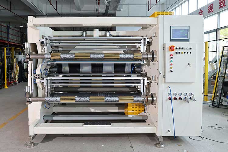
3. Transmission and correction system calibration
Ensure that the material is always in the correct position during operation.
• Key components: guiding sensors (ultrasonic, optoelectronic, CCD), guiding actuators (pneumatic/hydraulic/electric), and each transmission roller.
• Calibration Method:
1. Calibration of Guiding Sensors:
▪ Center Position Calibration: Manually adjust the edge of the material to the ideal datum position, executing the Learn or Set command on the correction controller to define this position as a datum.
▪ Sensitivity Settings: Adjust the detection sensitivity and response speed based on the flatness of the material's edges and the operating speed to avoid overreacting or slowing the system.
2. Calibration of the correction actuator:
▪ Check whether the cylinder/hydraulic cylinder is leaking/leaking oil, and whether the lead screw/guide rail is well lubricated.
▪ Calibrate the "median" and maximum stroke limits of the actuator.
3. Transmission roller parallelism and levelness:
▪ Using a high-precision level and dial indicator, check the levelness of all guide rollers and their parallelism to each other. Non-parallelism will cause the material to wrinkle and deviate.
• Recommended calibration interval:
◦ For each coil or material type: Recalibrate the guise correction sensor datum.
◦ Monthly: Check the actuator status and drive roller parallelism.
◦ Semi-annual: Perform a comprehensive inspection and calibration.
4. Pressure and pneumatic system calibration
The actions of many slitting machines such as pressing rollers and unloading are controlled by pneumatic systems, and the stability of pressure is crucial.
• Key components: air pressure regulating valve, pressure sensor, cylinder.
• Calibration Method:
◦ Use a calibrated digital pressure gauge, connected to a pneumatic circuit.
◦ Compare the pressure values displayed by the controller with the actual readings of the digital pressure gauge and correct them with the control valve or parameters inside the controller if there is any deviation.
◦ Check whether the cylinder is running smoothly, whether there is crawling, and whether the joint is leaking.
• Recommended calibration interval:
◦ Weekly: Visually inspect the pressure gauge readings.
◦ Quarterly: Compare calibration with standard pressure gauges.
Establish a complete calibration and maintenance system
1. Formulate a calibration schedule: Make a table of all the above calibration items, methods, standards, and periods, post them near the equipment, and strictly implement them.
2. Create a checklist: Before starting the machine every day, the operator will quickly check and record key parameters (such as tension display, air pressure, tool noise, etc.).
3. Documentation and Traceability: Detailed records of the time, personnel, results, and parameters adjusted for each calibration. This historical data is valuable for troubleshooting and predictive maintenance.
4. Train Operators: Allowing operators to understand the significance of each parameter and the consequences of deviations is the first line of defense for anomalies.
5. Spare Parts Management: Ensure that critical wearing parts (such as blades, bearings, magnetic powders) are in stock and replaced promptly when they reach the end of their useful life.
summary
The long-term stable operation of the slitting machine is a systematic project, and it must not be "heavy use and light maintenance". By establishing a regular and scientific calibration system with the four major systems of tension, tool, correction and pressure as the core, supplemented by perfect document management and personnel training, the accuracy of the equipment can be maintained to the greatest extent, the life of the equipment can be extended, and the production efficiency and product quality can always be at a high level. For complex electrical and servo system calibration, it is recommended to regularly hire original engineers for in-depth maintenance and calibration.
 Hot stamping film slitting machine operation guide: from beginner to mastery
 5 issues that must be considered before buying a hot stamping film slitting machine
 Full analysis of film slitting machine operation: the complete process from start-up to maintenance
 How to choose a hot stamping film slitting machine? Full analysis of key parameters
 The Strings of Tension: The Invisible Movement Behind the Precision Revolution in Ribbon Slitting Machines