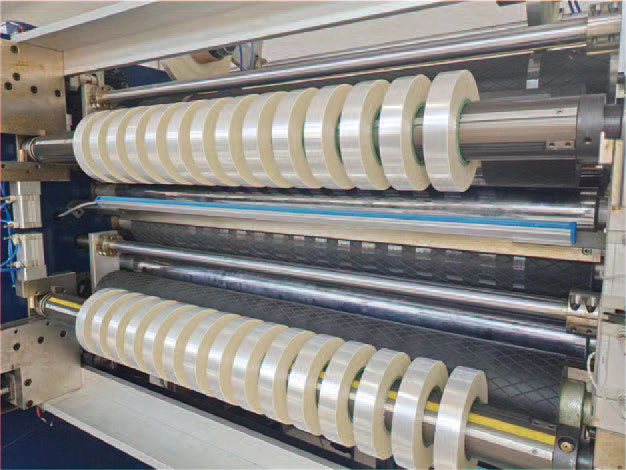
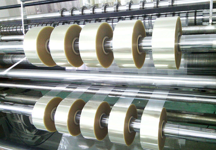
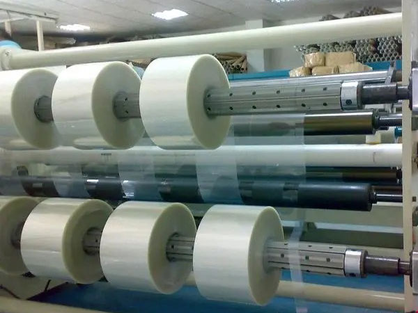
In the processing of PET film (polyester film), slitting is a key process in converting wide master coils into finished products of specific specifications. However, almost all slitting operators face a common nightmare: dust, static entanglement, and chip buildup.
It's not just about "looking dirty". Excessive dust and chips can lead to uneven product surfaces, white spots on subsequent printing or aluminizing, uneven winding end faces, and even scratches on the film surface in severe cases, resulting in a large amount of scrap.
This article will deeply analyze the causes of dust and static electricity in PET film slitting and provide a comprehensive treatment plan from "passive removal" to "active suppression".
1. Why does PET film slitting produce "dust"?
Many people mistakenly think that what is cut off by the slitting knife is "dust", but in fact it is mainly divided into two categories:
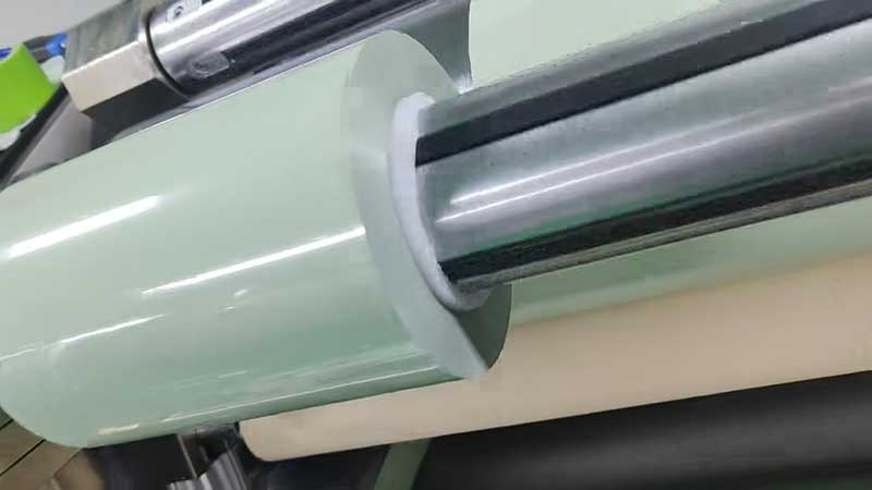
1. Chips (Dust): These are tiny plastic particles created by the slitting tool when the film is cut. PET film is smooth, but it contains anti-adhesion agents (opening agents) such as silica, and when the cross-section is cut, the shear force of the tool can cause trace amounts of material to fall off. Especially when cutting narrow bands (discs), the amount of chips increases significantly.
2. Environmental dust: The dust that originally exists in the air is adsorbed on the surface of the film due to static electricity.
2. The main pain points in the slitting process
In the high-speed slitting process (usually 100m/min-400m/min), there are three main technical problems:
Pain point 1: Electrostatic interference
PET film is an insulator with extremely high resistance. During unwinding, winding and high-speed frictional separation from the rollers, extremely high static voltages (thousands to tens of thousands of volts) are generated.
• Consequences: Operators are prone to electric shock, film adsorption on the equipment deviation, winding and slipping, causing wrinkles, and even causing fire or electronic control system failure.
Pain point 2: chip attachment
Once the chips are produced, they will float around. Due to the adsorption force of electrostatic electricity, these particles adhere firmly to the surface of the film.
• Consequences: During post-processing (e.g., aluminizing), these particles fall off to form "fisheyes" or pinholes; If it is used for capacitor films, it may result in a decrease in the breakdown voltage.
Pain point 3: Dust accumulation
Chips and dust mix and accumulate on the tool slots, guide rollers and tables. Cleaning requires frequent downtime, which seriously affects production efficiency.
3. Systematic solutions: from "removal" to "prevention"
To completely solve this problem, it is not possible to rely on a single device alone, but to build an active dust suppression + physical removal system.
1. Efficient static removal solution (elimination of adsorption)
Since static electricity is the culprit of dust adsorption, it is first necessary to neutralize static electricity.
• Active Static Eliminator (Ion Rod):
◦ Installation position: A long-distance ion rod must be installed immediately after unwinding and unwinding to neutralize the static electricity accumulated by the mother coil due to long-term storage; It must also be installed before winding to prevent air and dust from being caught in the winding.
◦ Recommended type: For high-speed PET slitting, it is recommended to use pulsed DC AC ion rods, which have higher power dissipation efficiency, no impact feeling, and are less likely to generate sparks than ordinary power frequency AC rods.
• Contact electrostatic brushes (copper/carbon fiber brushes):
◦ Before the film enters the tool shaft, a grounded conductive brush is installed to directly physically derive part of the static electricity as a supplement to the ion rod.
2. Source control: Optimize slitting tools and tool grooves
The amount of chips generated is directly related to the sharpness of the tool and the fit of the slot.
• Tool Management:
◦ Material upgrade: Use ultra-fine carbide inserts to keep the edge sharp for a long time. Blunt knives can pull instead of shear, resulting in a dramatic increase in chip volume.
◦ Angle Adjustment: Adjust the insert angle based on the film thickness, ensuring a "slip" rather than a "squeeze".
• Toolstroke Roll Optimization:
◦ Spiral grooves: Traditional straight grooves are prone to clogging of dust, causing the edges of the film to jump. The use of spiral groove rollers can guide chips to be discharged along the spiral during rotation, reducing accumulation.
◦ Vacuum adsorption slot slot: For ultra-thin films or high cleanliness requirements, vacuum slot rollers with micro-perforated or groove connections can be used to suck up chips while rotating.
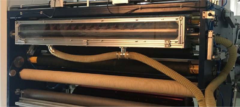
3. Core weapon: online dust and chip collection system
This is the part of the "visible" effect. It is necessary to design the negative pressure suction duct according to the width of the equipment.
• Double-sided nozzle design:
◦ Suction type: Fits snugly above the slitting cutter head to suck up floating chips.
◦ Down/side suction: align the contact point between the cutter channel roller and the film to directly suck away the particles that have just been generated and have not been re-adsorbed by static electricity.
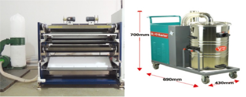
• High Pressure Fans and Filtration:
◦ Medium/high pressure fans are used to ensure that each air inlet has sufficient negative pressure (wind speed is recommended to be more than 25m/s).
◦ The rear end is equipped with a dust collection box or pulse filter cartridge dust collector to prevent the secondary discharge of dust into the workshop environment.
4. Auxiliary means: cleaning roller and sticky dust roller
For stubborn dust that remains after the above treatment, a final level can be set before entering the winding.
• Principle: The sticky dust roller (similar to oversized tape) made of special polymer material is in contact with the film surface and takes away the residual dust through adhesion. It is usually used with a peeling roller to transfer the dirt on the surface of the sticky dust roller to the peeling roller to achieve automatic cleaning.
• Note: The contact pressure should be controlled to prevent the film from stretching and deforming or indentation.
4. Example of scheme layout (recommended process)
To make the scheme more intuitive, a typical high-precision PET film slitting machine should have the following layout:
1. Unwinding unit: install high-power ion air rod + contact antistatic brush.
2. The first dust removal point (coarse dust removal): Before entering the first guide roller, install a vacuum vacuum duct to absorb most of the unwinding dust.
3. Slitting Unit (Core Area):
◦ The front and rear of the tool holder are equipped with side suction ports.
◦ Brush sweeping device + bottom vacuum port installed on the bottom of the groove roller.
4. Flattening and conveying: Install ion rods to prevent dust from secondary friction of the film caused by electrostatic adsorption rollers.
5. Final Cleaning Unit (Before Rewinding):
◦ Configure a pair of sticky dust rollers (up/down contact).
◦ Install the ion rod again to completely eliminate static electricity and ensure that the winding is neat.
5. Conclusion
In the field of film packaging, photoelectric display or new energy materials, cleanliness has become a core indicator of product quality. In the face of the problem of "too much dust", simple cleaning is the symptom rather than the root cause.
A successful PET film slitting treatment solution must follow the logic of "neutralization first, then adsorption, then collection":
• Static removal is the physical premise for solving dust adsorption;
• Optimized tools reduce dust generation at the source;
• Vacuum adsorption is the physical means of removing dust chips.
Through the above comprehensive management, not only can the cleanliness of the slitting workshop be improved to a higher level, but also effectively improve product yield and reduce customer complaints. If your slitter is currently just wiping knives with a rag or letting dust drift, it's time to consider upgrading your dust collection system.
 What should you do if the film slitting machine wrinkles? A comprehensive analysis from root causes to countermeasures
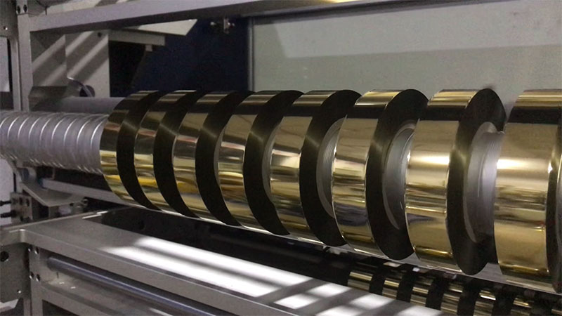 Key points for debugging PET/aluminum foil composite hot stamping foil slitting machinesFilm Slitting Machine Innovation Rankings: Five Breakthroughs to Watch in 2026
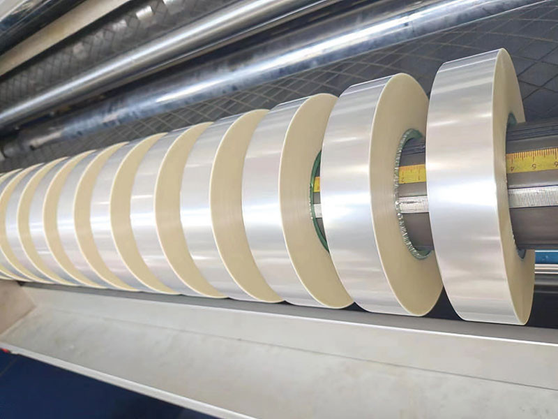 Film slitting machine technology trends: quieter, more stable, and more durableDon't just look at the price of film slitting machines: the full lifecycle cost is the key to cost reduction


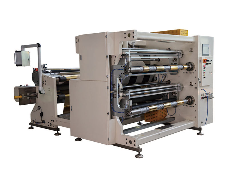 1400mm Hot Stamping Foil Slitting Machine
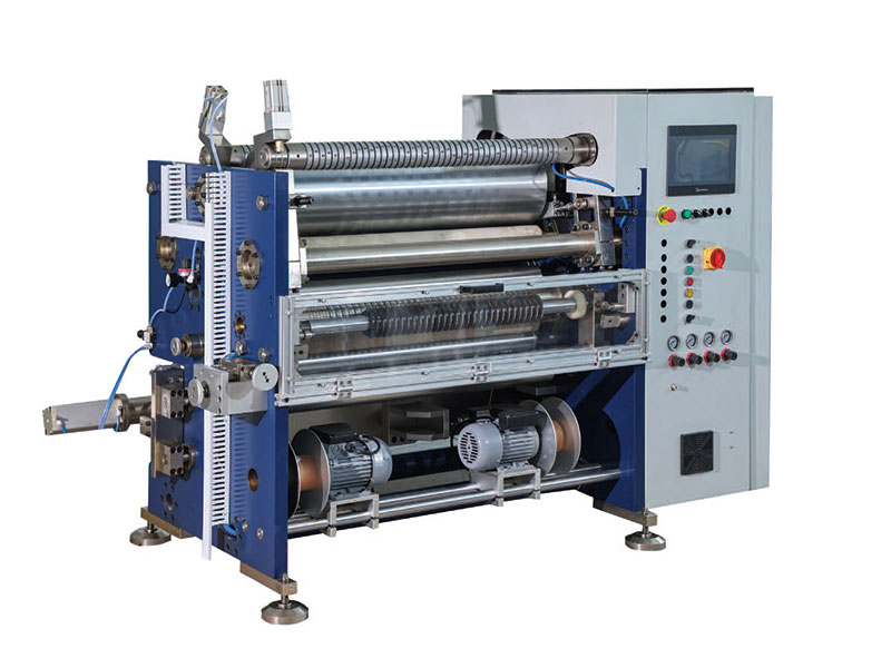 800mm Hot Stamping Foil Slitting Machine
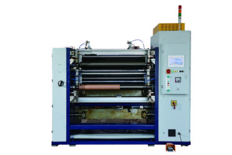 New Energy Ultra-thin Film Slitting Machine For Capacitive Film
 1350mm Hot Stamping Foil Slitting Machine