In the slitting process of ribbon (heat transfer ribbon), the automatic deviation correction system is the core device to ensure the slitting accuracy and reduce material loss. If the guiding system is not properly debugged, it is very easy to cause problems such as deviation, uneven winding, edge burrs and even broken ribbons. This article takes the ultrasonic/photoelectric edge correction system as an example to explain the standard debugging process in detail.
1. Preparation before commissioning
1. Security confirmation
• Cut off the main power supply and hang the "debugging" warning sign.
• Confirm that the emergency stop button and protective cover sensor are functioning normally.
2. Tools and materials
• Allen wrench, multimeter, screwdriver.
• Equipment manual, correction controller manual (such as Leimer, Merces and other brands).
• Standard width ribbon for testing (recommended to be consistent with production specifications).
3. Mechanical condition check
• Guide roller cleaning: all guide rollers have no glue stains or scratches on the surface, and rotate flexibly.
• Bearings and slide rails: the slide rail of the corrective frame has no foreign object jamming, and the manual push and pull should be smooth and without gaps.
• Air circuit inspection: If it is pneumatic correction, confirm that the air pressure is stable at 0.4-0.6MPa and there is no air leakage.
2. Sensor installation and calibration
1. Sensor type confirmation
• Ultrasonic: Suitable for transparent or non-transparent substrates to detect edges.
• Photoelectric type: The color difference between the edge and the background should be obvious (such as black ribbon versus white guide roller).
2. Installation location
• The sensor should be installed in front of the correction frame (feeding side), about 30-50cm away from the correction frame, to ensure that the detection point can reflect the deviation trend in advance.
• The sensor emission surface is perpendicular to the edge of the strip and is located directly above or below the strip running plane (depending on the model).
3. Zero point calibration
• Thread and straighten the ribbon so that its edge falls exactly at the midpoint of the sensor's detection range (most controllers have an LED indicator or display position).
• Press the "Zero Setting" or "Auto Zero" key on the controller, at which point the controller should display "0" or the midpoint position voltage (e.g., 2.5V).
4. Gain and sensitivity adjustments
• Ultrasonic sensor: adjust the gain knob to make the signal the maximum value when there is no band, and stabilize at 30%-70% range when there is band.
• Photoelectric sensor: Adjust the light source intensity to ensure that the signal difference between the edges and unoccluded is greater than 2V (analog quantitative).
3. Commissioning of the executive agency
1. Drive orientation confirmation
• Manually push the corrector to one side and observe whether the position feedback value on the controller panel changes accordingly.
• Move the "Shift Left/Shift Right" button to confirm that the direction of movement of the corrector is consistent with the button. If it is reversed, the output polarity of the motor or proportional valve needs to be modified in the controller.
2. Dead zone settings
• Dead zones refer to the "no-correction" areas allowed by the controller. Too small will cause the correction frame to shake frequently, and too much will reduce the accuracy.
• The initial setting is ±0.2mm, and the action frequency of the correction frame can be observed when the equipment is running at low speed, and can be appropriately increased to ±0.3mm if the jitter is violent.
3. Responsiveness matching
• Low-speed slitting (≤50m/min): The response speed is adjusted to medium to avoid overtuning.
• High-speed slitting (≥150m/min): The response speed needs to be adjusted to the fastest, but it needs to be combined with mechanical rigidity to prevent oscillation.
• Most controllers are adjusted by "gain" or "proportional band" parameters: the larger the gain, the more sensitive the correction, but it is easy to oscillate.
4. Simulation operation and fine tuning
1. Strip-free air running test
• Remove the ribbon and let the equipment idle to observe whether the correction frame is stationary. If there is drift, recalibrate the sensor zero point or check the mechanical level.
2. Low-speed strap penetration test
• Running at a speed of 10-20m/min, the ribbon is artificially pushed to one side to see if the correction frame can quickly pull it back to the midpoint.
• Record the "maximum offset" which should be less than 1.5 times the set dead zone.
3. High-speed dynamic fine-tuning
• Gradually increase the production speed (e.g. 200 m/min) and observe the end face neatness at the winding point.
• If the end face shows a "spiral" staggered layer, it means that the correction response is too slow and the gain needs to be increased.
• If there is a "wavy" high-frequency jitter on the end face, it means that the gain is too large or the dead zone is too small, and a callback is required.
5. Common problems and countermeasures
| phenomenon | Possible causes | Treatment method |
| The correction frame oscillates frequently | Dead zones are too small/gain is too high | Increase dead zones and reduce buffs |
| The response is lagging behind and the deviation is not corrected | Insufficient sensor sensitivity | Clean the sensor and reset the zero point |
| The unilateral limit of the correction frame is stuck | Limit switch failure/zero drift | Check the limit and recalibrate the midpoint |
| High-speed deviation, low speed is normal | Mechanical resonance/guide roller parallelism difference | Check the horizontality of each guide roller and fasten the footing |
6. Debugging records and acceptance standards
After debugging, the following parameters should be recorded and archived:
• Sensor model and mounting location.
• Controller key parameters (dead zone, gain, response speed).
• The maximum amount of deviation at each speed section.
Acceptance criteria (refer to general industry requirements):
• The neatness deviation of the winding end face after slitting is ≤ ±1mm/100mm roll width.
• The guiding system has an edge fluctuation amplitude of ≤ ±0.5mm at maximum speed.
Epilogue
The commissioning of the automatic deviation correction system is a "delicate job", which requires the commissioner to have a comprehensive understanding of mechanical, electrical, and technological skills. Follow the principle of "mechanical before electrical, static first and then dynamic, low speed first and then high speed", and patiently verify item by item to optimize the slitting accuracy and efficiency. It is recommended that operators clean the sensor and lubricate the guide rail of the correction frame on a daily basis to maintain the stability of the system for a long time.
Note: The interface and parameter names of different brands (such as BST, FIFE, RE, etc.) are slightly different, but the underlying logic is the same, please refer to the operation manual of the corresponding model when debugging.
 How to choose a ribbon slitting machine? A comprehensive explanation of speed, precision, and costRibbon slitting machine tension control techniques: From beginner to expert
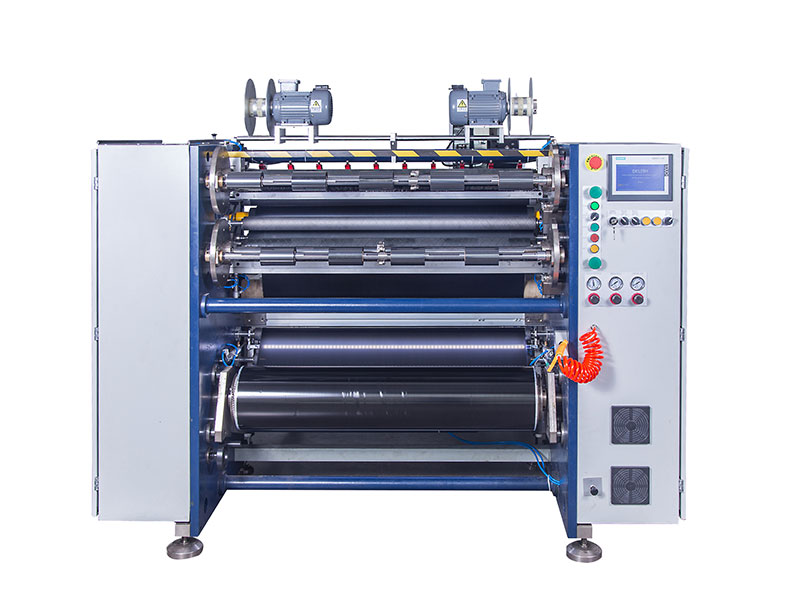 How can ribbon slitting machines improve production efficiency by 40%? Analysis of three core parametersRibbon slitting machine material-saving secret: Block every bit of loss at the sourceHow to control the precision of a ribbon slitting machine?


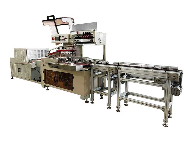 Thermal Transfer Ribbons Packaging Machine
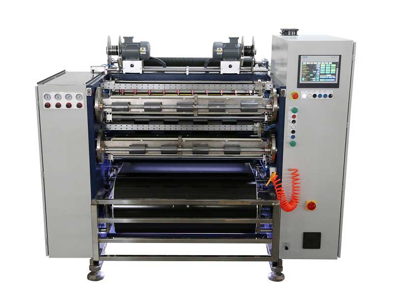 Automatic Thermal Transfer Ribbon Slitting Machine RSDS8 H PLUS
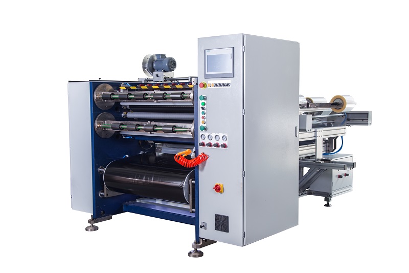 Semi Automatic Thermal Transfer Ribbon Slitting Machine RSDS5 PLUS
 Automatic Thermal Transfer Ribbon Slitting Machine RSDS8 PLUS