
In the production of thermal transfer ribbons, the quality of the slitting process directly determines the final printed result. Tension control is the most core and easily overlooked variable in the slitting process. The PET base film thickness of the ribbon is usually only 4.5-10μm, making it extremely sensitive to tension changes—excessive tension causes the base film to stretch and deform, causing microcracks in the ink layer, leading to powder shedding and white print lines; If the tension is too low, the ribbon becomes loose and wrinkled, unevenly rolled, and the end face becomes serpentine. This article will focus on key data for tension adjustment, systematically reviewing parameter ranges, zonal control strategies, and common fault troubleshooting methods for different ribbon materials.
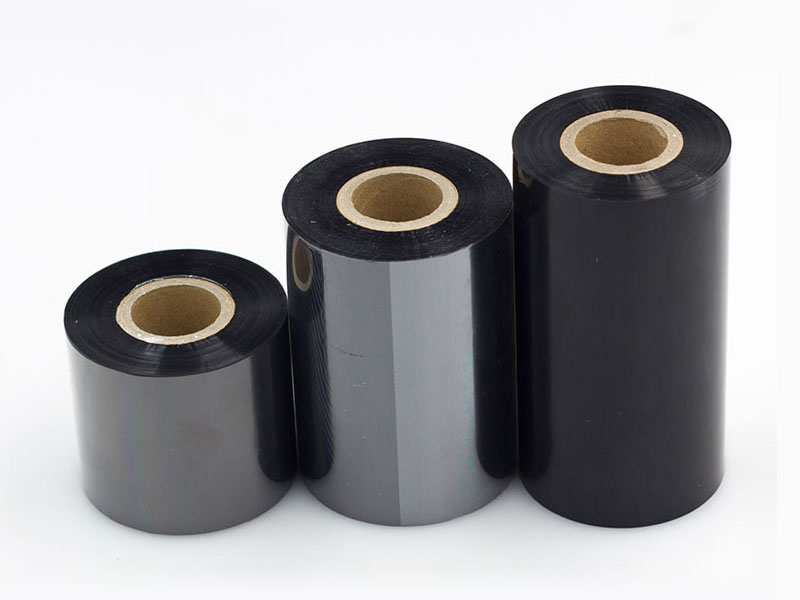
1. Tension reference data for different ribbon materials
Different types of ribbons have significant physical properties, and tension parameters must not be "one-size-fits-all." Below are the recommended tension ranges summarized based on industry practice:
| Carbon ribbon types | Recommended tension range | Notes |
| Wax-based ribbons | 2-5N | The texture is relatively soft and requires low tension combined with an electrostatic eliminator to prevent sticking |
| Mixed-base carbon ribbons | 5-8N (some devices can reach 5-15N) | Medium tension requires temperature control (20±2°C) to prevent resin layer cracking |
| Resin-based ribbons | 8-12N (some high-hardness pigment formulations can reach 15-30N) | Higher tension is needed to ensure flatness, but attention must be paid to the stretch limit |
| Narrow band slitting (<10mm) | 60%-70% of conventional broadband | It has extremely weak lateral rigidity and is highly sensitive to tension fluctuations |
The core principle is the "minimum feasible tension"—using the smallest possible tension value to minimize the risk of base film stretching while ensuring smooth ribbons run smoothly, without slipping or deviation.
2. Differentiated control parameters for three-segment zoning
The entire slitting line is not "all the way through with a single tension value." An excellent tension control solution divides the equipment into three independent control zones, with the following target tension setting strategies for each zone:
• Unwinding area: uses a decreasing tension curve. As the roll diameter decreases, the tension should decrease accordingly to prevent inner layer relaxation or material stretching. The initial tension is set as a reference value and automatically adjusts according to decreasing scale changes in roll diameter.
• Slitting zone: In this area, the ribbon has the greatest friction resistance when passing through the groove, requiring slightly higher tension to maintain stable cutting. It is usually set to 10%-15% lower than the tension in the unwinding zone, and a floating roll buffer mechanism is added to absorb instantaneous fluctuations.
• Winding area: Uses a taper decreasing control strategy—the initial tension is set at 120% of the slitting zone tension, which decreases linearly to 80% as the winding diameter increases. This prevents the outer layer from being too tight and crushing the inner layer, forming a "chrysanthemum core" winding pattern, ensuring consistent hardness between the inner and outer layers of the finished roll and a mirror-like flat edge.
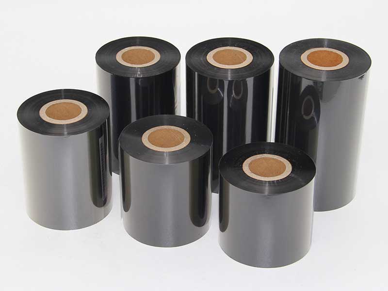
3. Accuracy Indicators of Closed-Loop Control Systems
Traditional open-loop control (such as manual adjustment of magnetic powder clutches) struggles to cope with tension fluctuations caused by changes in coil diameter, with fluctuations reaching up to ±10%. Modern high-precision slitting machines generally adopt a three-stage independent closed-loop tension control system:
| Control Stage | Actuators | Feedback methods |
| Release the paper | Magnetic powder brakes or servo motors | Real-time feedback from the tension sensor |
| Traction section | Servo motor drive | Encoder speed feedback |
| Collect the volume | Vector variable frequency motor | Tension sensor + PID dynamic adjustment |
Through dynamic adjustment via PLC and PID algorithms, high-end models can control tension fluctuations within ±0.5N, with tension sensor accuracy reaching ±0.1N. Some high-end models even introduce acceleration feedforward compensation during acceleration and deceleration to avoid sudden tension changes during start-stop moments.
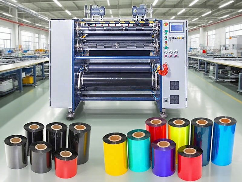
4. Troubleshooting and calibrating key data for tension instability
When tension fluctuations occur, it is recommended to follow the troubleshooting logic of "mechanical before electrical, no-load before load." The following are key calibration data standards:
Mechanical segments (accounting for over 60% of fault causes):
• The parallelism error of the guide rollers should be controlled within 0.05mm/m; otherwise, the ribbon may generate lateral component forces, causing uneven tension on both sides.
• It is recommended to maintain the air pressure of the expansion shaft at 0.5-0.6MPa, and the pointer should not shake; a pressure stabilizing valve should be installed in the gas circuit.
• The pressure on both sides of the pressure roller must be measured side by side with a pressure gauge to ensure consistent readings.
Electrical and parameter optimization:
• Magnetic powder clutch activation: After more than one year of use, magnetic powder may settle and clump; "magnetic powder activation" can be performed—no film penetration, low-speed idling, and run at 50% rated current for 10-15 minutes.
• PID parameter tuning reference: start with a small proportion (P=10-20%), gradually increase until a slight equal-amplitude oscillation appears, then pull back; Integration time starts at 5 seconds and is adjusted downward; The derivative value is set as 1/8~1/4 of the integration time.
• Acceleration and deceleration ramping time: It is recommended to set acceleration time to 3-5 seconds and deceleration time to 4-6 seconds, with fine-tuning based on the device's inertia.
Conclusion
There is no "universal formula" for tension adjustment; the key lies in understanding the "temperament" of different ribbon materials, establishing differentiated control thinking by section, and using closed-loop control systems to keep fluctuations within precise ranges. It is recommended that enterprises establish process parameter databases for each type of ribbon, standardizing the optimal tension value, taper curve, and acceleration/deceleration time to achieve "one-click call." This is the most effective way to improve yield rates and reduce defect rates.
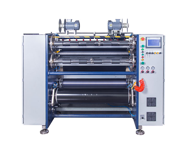 Can a barcode ribbon slitting machine cut and thermal transfer ribbons?
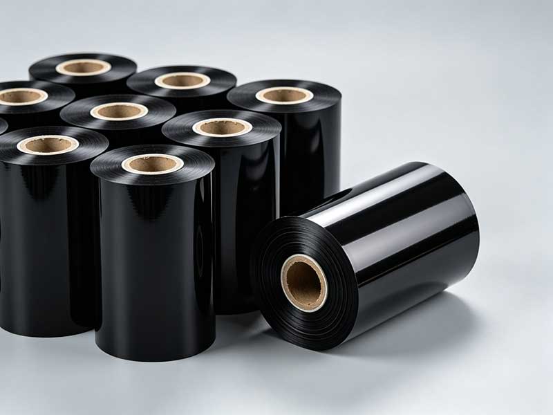 How to choose a barcode ribbon slitting machine? Core Features and Key Selection PointsCauses of uneven end faces in ribbon slitting machinesHow to solve wrinkled winding in ribbon slitting machinesRibbon slitting machine selection: wax-based, mixed-based, or resin-based


 English
 Deutsch
 Français
 Español
 Português
 日本語
日本語 русский
 한국어
한국어 عربي
عربي ภาษาไทย
 Tiếng Việt
 Italiano
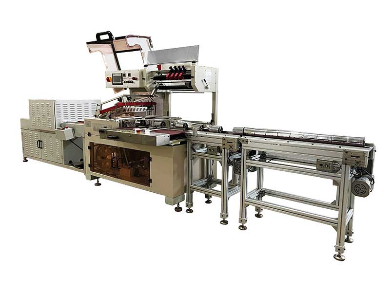 Thermal Transfer Ribbons Packaging Machine
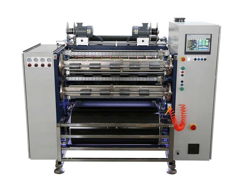 Automatic Thermal Transfer Ribbon Slitting Machine RSDS8 H PLUS
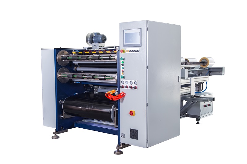 Semi Automatic Thermal Transfer Ribbon Slitting Machine RSDS5 PLUS
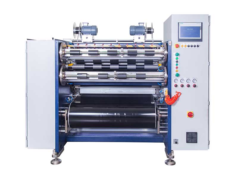 TTR Slitting Machine