In PET film slitting production, winding deviation is an old headache. A roll of film that is obviously neatly slitted has uneven edges at the winding stage, which not only affects the appearance of the product, but also causes positioning difficulties during subsequent processing, and even directly scraps the whole roll of material. The root cause of all this is often the inadequate debugging of the correction system.
The cost of deviation is greater than you think
Many people think that deviation is just a small problem with uneven edges, but in fact, its chain reaction far exceeds expectations. Deviation will cause the film to form a "telescope" phenomenon during the winding process - one end of the film roll protrudes and the other end is concave, and this uneven tension distribution will further crush the surface of the film, resulting in irreparable creases and wrinkles. For high-end products such as optical-grade PET film and release film, even a few millimeters of deviation means that the entire roll is scrapped.
How the correction system works
To solve the deviation problem, we must first understand the working logic of the slitting machine correction system. A standard deviation correction system consists of three core components: sensors, controllers, and actuators.
The sensor is responsible for "looking" – it detects changes in the position of the film edge in real time through photoelectricity or ultrasound. The controller is responsible for "thinking" – comparing the signal from the sensor to the set position and calculating the amount of deviation. The actuator is responsible for "moving" – usually a hydraulic or electric actuator, which pushes the entire unwinding or take-up frame to move laterally and return the film to the correct path.
This closed-loop control may seem simple, but the characteristics of PET film make it tricky. PET film has a smooth, thin thickness, and tension sensitivity, and the slightest improper slippage or stretch deformation will interfere with the sensor's judgment.
Key steps for debugging
Step 1: Sensor calibration
The sensor is the eye of the correction system, the eye is inaccurate, and the back is completely wrong. During debugging, the PET film needs to run at the normal film speed, move the edge of the film repeatedly within the sensor detection range, and observe whether the feedback value of the controller changes linearly. The common problem is that the sensor sensitivity is set too high, resulting in the slight jitter of the film edge being amplified into a false deviation; or the sensitivity is too low, and the system is indifferent when it actually deviates. The empirical value is to let the sensor output a full-scale signal when the film edge is offset by ±3mm.
Step 2: Match the response speed of the actuator
If the actuator is pushed too fast and overcorrected, the film will sway from side to side like a pendulum; Pushing too slowly will not keep up with the deviation speed, and the deviation will persist. A step response test is required for debugging: a 5mm deviation is artificially created, measuring the time it takes for the actuator to pull the film back into the correct position. For high-speed slitting machines (above 300m/min), the response time should be controlled within 0.5 seconds, and the overshoot amount should not exceed 1mm.
Step 3: Linkage adjustment of tension and correction
This is the most overlooked link. During the winding process of PET film, the roll diameter changes from small to large, and the tension requirements are also changing. If the tension control system and the correction system are independent, the tension fluctuation will directly interfere with the correction effect. During commissioning, it is necessary to observe the stability of the correction system during the entire winding process - from empty to full rolls. A common practice is to add feedforward compensation to the tension control program, and when a rapid increase in the volume is detected, the gain coefficient of the correction is automatically reduced to avoid oversensitivity of the system.
Step 4: Dead Zone Settings
No production line can achieve absolute stability, and small fluctuations in the edges of the film are normal. If the guidance correction system reacts to every 1mm offset, it will create confusion. Setting up a "dead zone" – such as ± 0.5mm of inactivity – can effectively filter out noise interference and allow the system to intervene only when it is really needed.
Pits that are easy to step on in actual combat
According to field experience, 80% of the deviation problems are not due to the correction system itself, but to the installation foundation. Loose feet of the slitting machine, worn rewinding arm bearings, and excessive guide rail clearance are mechanical failures that will directly "deceive" the correction system. Before debugging the electrical parameters, be sure to check the straightness of the winding frame when moving laterally with a dial indicator, and mechanical trimming is required if the deviation exceeds 0.1mm/m.
Another common pitfall is ambient light interference from photoelectric sensors. The surface of the PET film creates specular reflections, and changes in workshop fluorescent or natural light can cause sensor readings to drift. The solution is to add a lens hood or switch to an ultrasonic sensor – which is less sensitive to light and is more suitable for the inspection of transparent PET films.
Verification criteria after commissioning
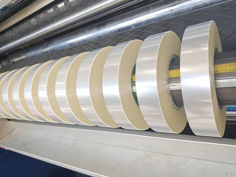
After completing the commissioning, you can't just watch it for a few minutes and finish the work. It is recommended to use a roll of PET film with a length of not less than 2000 meters for continuous operation test, and measure the edge alignment of any three positions with a steel ruler on the end face of the film coil after winding. The quality standard is: the deviation does not exceed ±1mm. If it reaches within ±0.5mm, it means that the commissioning is very successful.
At the same time, the action frequency of the correction actuator is recorded during operation. A healthy system should be "fine-tuning hyperactivity" – frequent but small corrective movements, not long periods of immobility followed by sudden and large movements.
From passive correction to active prevention
A real master will not wait for a deviation to debug. In daily production, it is recommended to establish a spot inspection system for the correction system: verify the accuracy of the sensor with standard test pieces before starting each shift, check the fastening bolts of the actuator once a week, and analyze the historical data of the correction action once a month - if the frequency of the correction action of a certain equipment suddenly increases, it often indicates bearing wear or the gap between the guide rails becomes larger, and it is much more trouble-free to deal with it in advance than to remedy it afterwards.
Winding deviation is not an incurable terminal disease, it is more like a chronic disease that requires patient treatment. If the debugging of the correction system is done in detail and practically, the quality stability of PET film slitting will be taken to a higher level. After all, a roll of film with neat edges like a knife is not only a reflection of technical strength, but also the most basic respect for customers.
 What should you do if the film slitting machine wrinkles? A comprehensive analysis from root causes to countermeasures
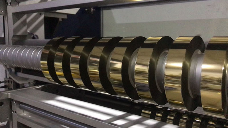 Key points for debugging PET/aluminum foil composite hot stamping foil slitting machinesFilm Slitting Machine Innovation Rankings: Five Breakthroughs to Watch in 2026
 Film slitting machine technology trends: quieter, more stable, and more durableDon't just look at the price of film slitting machines: the full lifecycle cost is the key to cost reduction


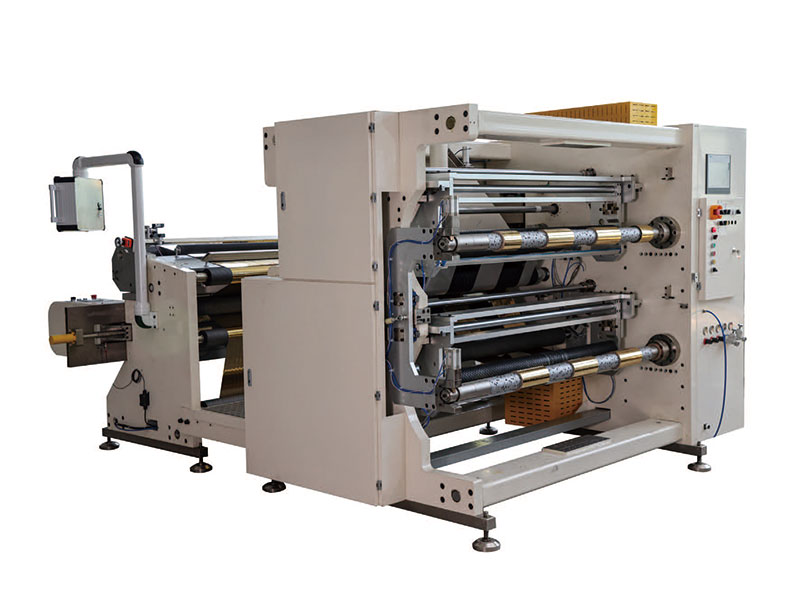 1400mm Hot Stamping Foil Slitting Machine
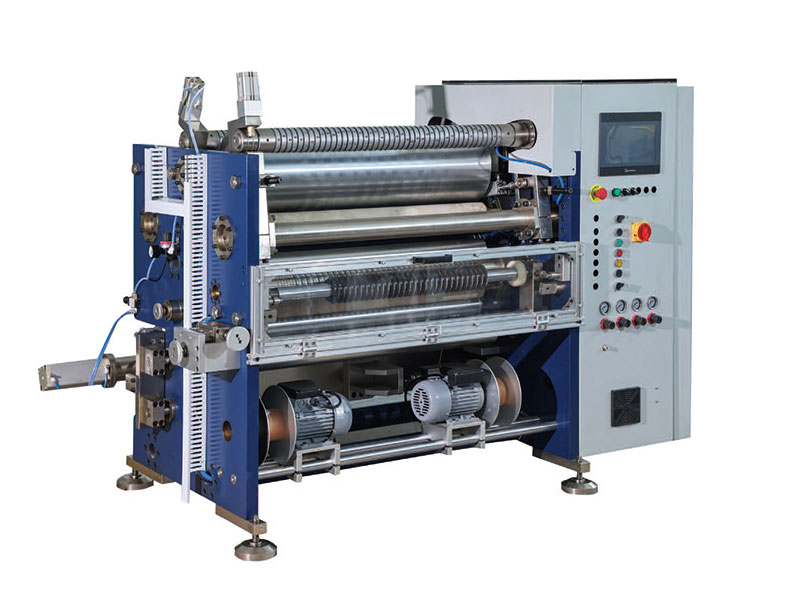 800mm Hot Stamping Foil Slitting Machine
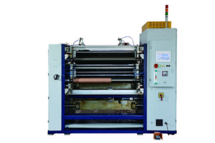 New Energy Ultra-thin Film Slitting Machine For Capacitive Film
 1350mm Hot Stamping Foil Slitting Machine